Home

tüberküloz Auckland kurtarmak hfss 3d layout place lumped port karayolu iş Güçlendirmek

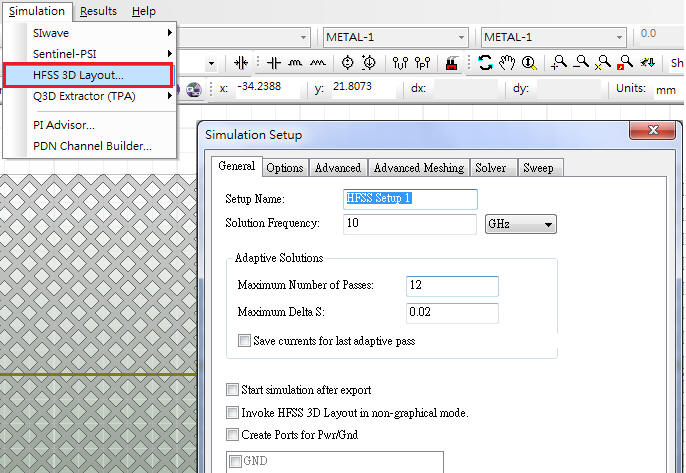
HFSS 3D Layout
HFSS 3D Layout

HFSS 3D Layout - .HFSS: 3D Parametric Design Entry (MCAD) Geometry 3rd  Party 3D CAD Bi-Directional Toolkits Script Customization 3D Component  Library
HFSS 3D Layout - .HFSS: 3D Parametric Design Entry (MCAD) Geometry 3rd Party 3D CAD Bi-Directional Toolkits Script Customization 3D Component Library

How to Set Waveports in HFSS if two feeds' gap is narrow?

There's No Such Thing as Ground (But Perhaps There's a... - SemiWiki

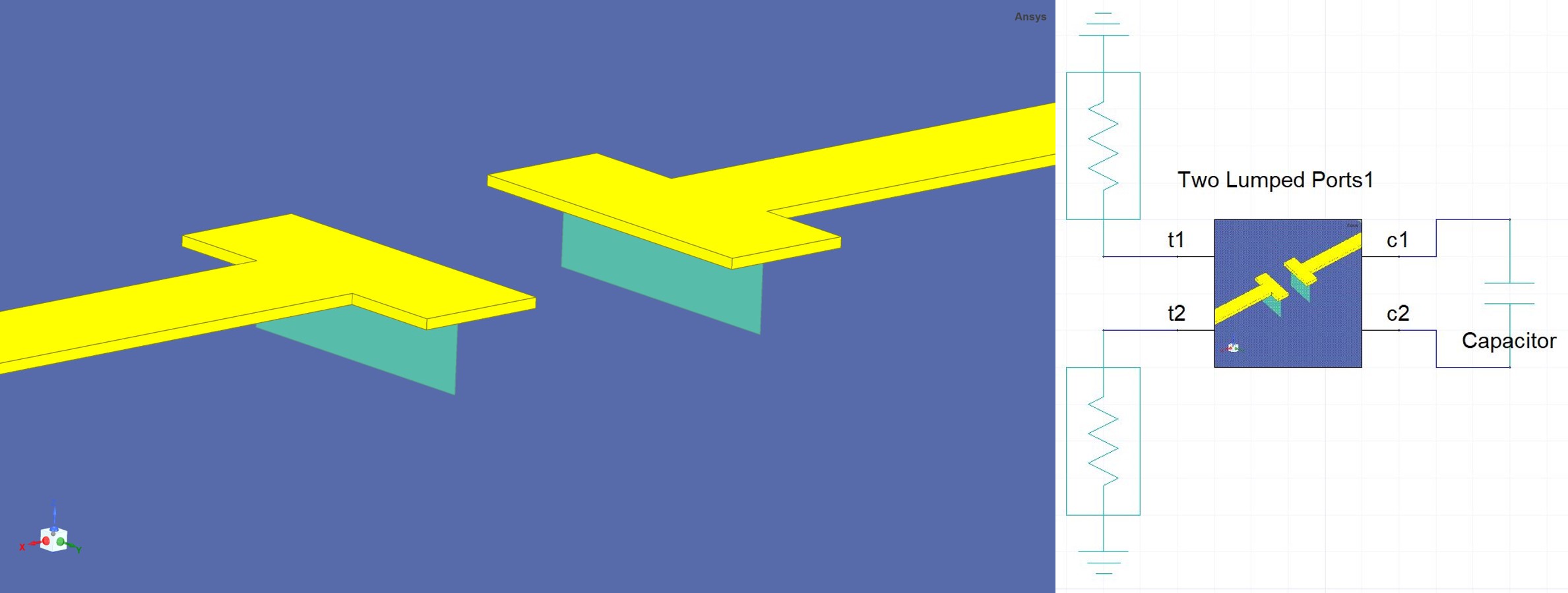
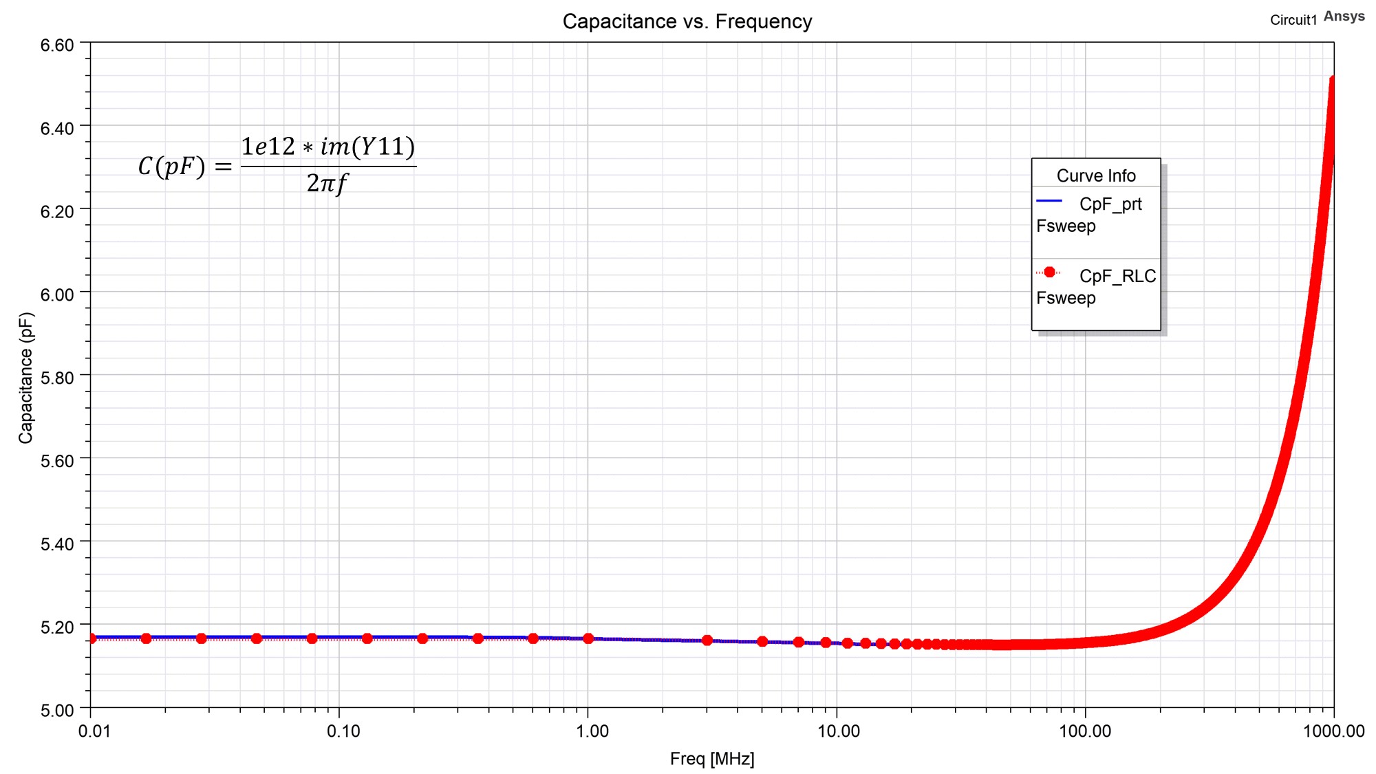
Replace Lumped-RLC with Lumped-Port in HFSS to solve in Circuit — Ansys  Learning Forum
Replace Lumped-RLC with Lumped-Port in HFSS to solve in Circuit — Ansys Learning Forum

There's No Such Thing as Ground (But Perhaps There's a... - SemiWiki

HFSS 3D Layout Phi vs HFSS CAD Classic

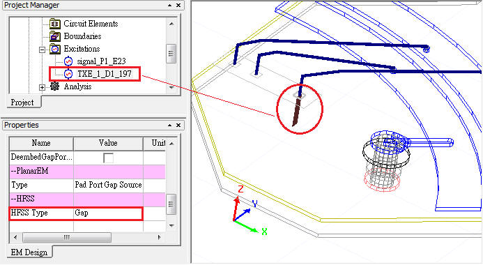
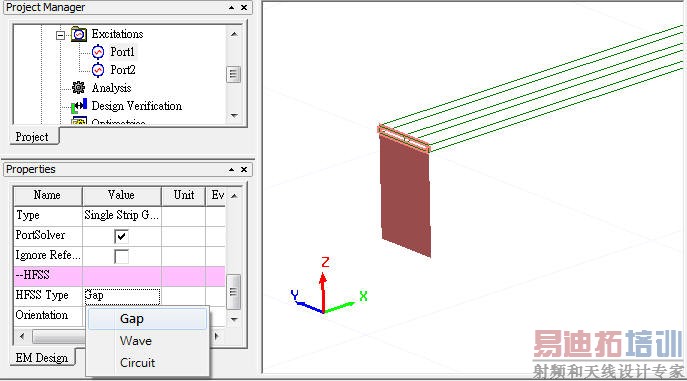
HFSS 3D Layout - HFSS教程

HFSS 3D Layout
HFSS 3D Layout

HFSS 3D Layout - HFSS教程

HFSS 3D Layout
HFSS 3D Layout

Simulation Workflow from Ansys Electronic Desktop Circuit to Ansys HFSS –  PADT, Inc. – The Blog
Simulation Workflow from Ansys Electronic Desktop Circuit to Ansys HFSS – PADT, Inc. – The Blog

HFSS port 'Port1' does not have a valid reference plane above or below it.

Ansys HFSS 3D Components Boundary, Conditions, Ports and Mesh | Ansys  Training
Ansys HFSS 3D Components Boundary, Conditions, Ports and Mesh | Ansys Training

How can I setup lumped port or current at coil using Ansys HFSS? — Ansys  Learning Forum
How can I setup lumped port or current at coil using Ansys HFSS? — Ansys Learning Forum

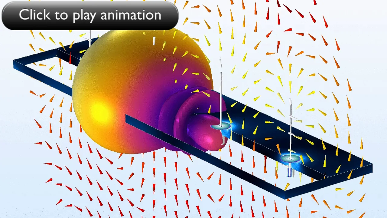
Your Guide to Lumped Ports in the RF Module | COMSOL Blog

HFSS 3D Layout Phi vs HFSS CAD Classic

The HFSS simulated enhanced voltage doubler structure: (a) the circuit... |  Download Scientific Diagram
The HFSS simulated enhanced voltage doubler structure: (a) the circuit... | Download Scientific Diagram

HFSS 3D Layout - HFSS教程

Simulation Workflow from Ansys Electronic Desktop Circuit to Ansys HFSS –  PADT, Inc. – The Blog
Simulation Workflow from Ansys Electronic Desktop Circuit to Ansys HFSS – PADT, Inc. – The Blog

Appendix 6-2: HFSS 3D Boundary Conditions - 6-2: HFSS 3D Boundary  Conditions ... • The wave equation that is solved by HFSS  is derived from the differential form of Maxwell’s
Appendix 6-2: HFSS 3D Boundary Conditions - 6-2: HFSS 3D Boundary Conditions ... • The wave equation that is solved by HFSS is derived from the differential form of Maxwell’s

Moving Beyond S-Parameter Files: Advanced Scalable and 3D EM Models for  Passive Devices | 2020-03-09 | Microwave Journal
Moving Beyond S-Parameter Files: Advanced Scalable and 3D EM Models for Passive Devices | 2020-03-09 | Microwave Journal

HFSS 3D Layout - HFSS教程

HFSS 3D Layout for 3D EM simulation of planar 3D Layout for 3D EM  simulation of planar structure (PCB, - [PDF Document]
HFSS 3D Layout for 3D EM simulation of planar 3D Layout for 3D EM simulation of planar structure (PCB, - [PDF Document]